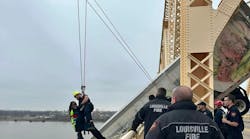
Many fire departments provide much more than suppression activities in the emergency services, including technical rescue. In the world of rope rescue, the rescue team still has to move a victim up, down, left, right, in a horizontal or vertical position to effect the removal of the injured party (Photo 1). Having limited staffing means we must use our systems or “machines” to maximum efficiency. So this month, we will discuss the use of mechanical advantage systems and safety/belay systems for the first arriving companies.
How much “energy” is available?
Moving a victim from a precarious situation will require some form of energy to accomplish. On the rescue scene, determining the type of system required to move the victim will be directly dependent on the amount of “energy” available. Now, in the world of rescue, when we have to lift or move significant-sized objects, we have to consider many variables that would limit movement, such as friction, size, density and weight, but for the purpose for our discussion we will focus on the potential weight of the victim for consideration in the rope rescue arena.
Any type of machine requires some form of energy to operate. Vehicles run on fuel, appliances run on electricity and humans run on hydration and nourishment; that being said, the size of the crew that is available on-scene to operate systems will have to be considered when calculating mechanical advantage systems.
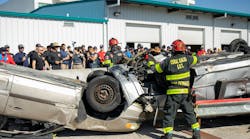
As a rule, the average human rescuer can apply 50 pounds of force (lbf) pushing or pulling an object. While easily open for debate, this average is used due to the nature of the incident; it may be possible that crews will operate within long operational periods and experience fatigue; on wet, sloped flooring; with debris piled around the rescue scene; and keeping good lifting techniques in place to avoid injury (Photo 2).
Calculating the “advantage”
Mechanical advantage (M/A) systems are force multipliers on a load based upon the use of simple machines (pulleys, in the rope world). Simply put, it is the difference between the force applied to perform the work and the actual force that is produced (Photo 3).
Tallying the potential energy of a five-member crew, the stored energy of the company would be 250 lbf for the crew. However, when that crew applies its force to a 5:1 mechanical advantage system, the output can total up to 1,250 lbf. Depending on the weight of the victim (and sometimes the additional weight of the rescuer, such as in an attended litter scenario), the correct amount of people can be matched to the correct size of the mechanical advantage system (Photo 4).
Let’s assume we are moving a victim who weighs approximately 300 pounds, packaged. If using a pulley system with a M/A system of 4:1, it will require a force of only approximately one-quarter of the load (approximately 75 lbf), plus the amount of energy required to get the victim into motion in the desired direction.
There are trade-offs to using M/A; the primary trade-off is the amount of materials used. For example, moving a victim 50 feet with a 3:1 M/A system would require a minimum of 150 feet of rope, plus any additional amount that would be needed to re-direct the rope back down to the crew applying the force. Additionally, a braking system will be needed in the event the victim is in motion and the control end becomes free, requiring more equipment and perhaps more rope, dependent on the location of the anchor for the braking system.
There is also a difference between theoretical and actual mechanical advantage. M/A systems are referred to as rated to their theoretical M/A; that is, there isn’t any consideration for the friction that is present in the system when it is assembled. Even a truly efficient system would take roughly 10% efficiency away for each pulley and approximately 2-3% for each bend in the rope. Taking that into consideration, the actual M/A for that 3:1 may only be a 2.7:1 (estimated), but the principle is the focus in the equation (Photo 5). The principle here is that the M/A allows the rescuers to use less force to move the load by spreading the work out over time and distance.
Calculating the system
The ease of calculation for M/A systems involves the pulleys. For our discussion, we shall refer to two types of pulleys; traveling pulleys and stationary pulleys. Stationary pulleys, or change-of-direction (COD) pulleys, are anchored in place and do not travel when the load is in motion. Their function is to re-direct the rope to move as the load is displaced. This type of pulley produces no mechanical advantage (1:1), but in a direct overhead position, it can compound the weight of the load onto its anchor spot (Photo 6). The Traveling Pulley is connected to either the load being moved, or to one of the ropes that is attached to the load being moved. Each pulley, when traveling, provides a 2:1 M/A for the system moving the load (Photo 7).
So how much system do we need? Take into account the victim (load), the distance to be traveled and the capabilities of the crew (machine) available. For example, a four-member rescue crew arrives on scene and must move a 300-pound victim 50 feet. Without the use of an M/A system, the crew would not have the ability to move the victim with just brute strength. If a 3:1 M/A system is used, the load is divided by three and the overall weight to be moved would be 100 pounds plus the necessary force required to get the victim in motion. If a 4:1 M/A system is used, the load is divided by four and the overall weight to be moved would be 75 pounds plus the necessary force required to get the victim in motion. Both scenarios should be easily manageable with the available energy within the “machine.”
Maximum output with limited input
The efficient use of mechanical advantage systems are based upon the foundation of some basic rules. When we build pulley systems, a good practice is to start with the terminal end (last part) of the rope to be used. Determining where this end is attached aids in determining the total M/A for the system. In even-numbered systems, the terminal end is connected to the anchor; in odd-numbered systems, the terminal end is attached to the load (Photo 8).
Depending on the type of system (simple, compound or complex), traveling pulleys and COD pulleys are arranged to provide the most efficient amount of output with minimum input. These pulleys can be arranged to work in parallel, compounding (stacking) or a combination of same.
Simple systems use a basic number of non-anchored moving pulleys to gain advantage. Compound systems utilize multiple pulleys in a different fashion; one pulley creates the initial advantage while attached to the load, and additional pulleys connect to the haul line from the previous pulley, therefore compounding the advantage gained by the first pulley (Photo 9). Complex systems are combinations of simple and compound systems. These are mostly utilized when during specialized applications when larger items need to be moved, and these systems provide a large amount of M/A (Photo 10). Either way, the system is constructed based on the needs of the haul and the available amount of force (energy) to operate the system.
The second line
Most rope folks will tell you, at least on this side of the rock, a second line, or a belay system, should be in place anytime someone is traveling up or down a rope in the event of a main line system failure. The belay system is a secondary rope that uses some type of stop system, whether it is a knot, device or a separate rope grab, that halts the progress of the victim or rescuer on the main line (Photo 11).
There are some options to the type of belay used. Many rescue teams use a top belay, which is secured to an anchor object from above, that uses its own rope, friction device and operator that is independent from the main line system. The idea here is that the secondary system can protect the crew or the victim from almost any possible failure.
Many teams utilize a bottom belay operator, who tensions the main line while the rappelling person is traveling down the mainline. While it may be an efficient way to stop forward progress, it would not be of much use in the event the main line or its anchor fails.
Conclusion
This is just the tip of the introduction of mechanical advantage systems. It is highly recommended that a strong training program, complete with a sound overview of system engineering, coupled with hands-on practical applications of these systems in use, is sought out and engaged for the members of your department. Additionally, continuing education in this field of expertise is a must-have in order to stay safe, efficient, and well versed in this skill; to accept anything less can result in catastrophic failures and injuries.
A future article will discuss the use of lowering systems in the rope rescue world and some simple patient packaging techniques for rapid victim placement and removal.