Renewable energy systems, especially solar photovoltaic (PV) systems, are here to stay. As such, the fire investigation community must adapt to this technology, similar to what had to be done with hybrid electric vehicles, with regards to both fire suppression and cause and origin investigative techniques.
As part of the investigator's “toolbox,” a fire investigator should be familiar with the solar PV installations within their jurisdiction. From here, a property list can be compiled and an investigative pre-plan can be developed. This list should include a “special call’ list of technical advisers as well.
When investigating fire incidents that involve solar PV systems, there are a number of factors to take into consideration. The most basic of considerations is to look at the fire scene objectively, ruling out all other possible causes. Investigation efforts should be directed to all potential causes and sources of ignition, ruling each one out in a methodical and systematic approach.
When approaching a fire that may potentially involve solar PV, the investigator must start by determining whether the fire cause and origin was as a result of the solar PV system itself or if there were other contributing factors. Was there an outside ignition source? As an example, in the case of a solar PV ground array incident, did the fire start from an external source, such as grass or vegetation fire? In the case of a parking canopy, was the cause and origin the car underneath?
After ruling out all other possible sources of ignition, and the evidence guides you into the direction of the solar PV system, then treat it as an electrical fire and look for electrical causes.
Common causes of solar PV fires
A primary cause of solar PV fires is electrical arcing, which occurs over high-voltage direct current (DC) lines. This occurs anytime there is a compromise of the electrical system's wiring or connections. There is an increased risk over time for arcs to occur. This can be attributed to the normal “wear and tear” that a solar PV system is subjected to which makes system maintenance a priority.
There are many factors that contribute to this condition:
- Corroded cables and connections
- Loose wiring between junction/splice boxes
- Improper cable support
- Animals chewing on wires
- Improper grounding (leading to a ground fault, phase to ground)
- Ground fault “blind spot” that manifests itself at too low of a level for the ground fault device to operate
- ARC fault (phase to phase)
There are three types of faults:
- Series—connections pulled apart
- Parallel—insulation breakdown between conductors
- Ground—compromise of an insulation system
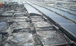
There have been cases where once a fire has started on a roof, it will reach into the roof assembly and travel. The fire spread is greater in a roof array than a standalone roof assembly. The potential exists for the PV wiring to cause ignition of the roof assembly. Once started, the flame propagation, which is determined by the type of roofing material and insulation, can be redirected by the configuration of the solar racking system.
That is the primary reason for a solar PV rooftop racking system to have a Class A fire rating. A Class A fire-rated roof racking system is configured so as not to substantially alter the fire rating of the roof. A lower rating’s class would change the method of fire spread that would in turn lower the roof fire rating. In order for a racking system to receive a Class A rating, it must pass a “Burning Brand Test” (ASTM E-108). Roof insulation is combustible and typically made up of polyurethane or polystyrene foam. DC arcing can be a source of ignition for these types of building materials.
Another potential source of a fire could be the solar module itself. It could have manufacturing defects that, over time, cause internal “hot spots.” The plastic backsheet of the module could be compromised, which can expose conductors. Look for tears, holes or cuts.
The key to fire prevention in a rooftop racking system is wire management. Sharp edges of the racking system could compromise the insulation of the string wiring causing a possible short circuit. Mislabeling of conductors, or no identification at all, can lead to incorrect wiring and terminations leading to a short circuit. The incorrect use or lack of installation of expansion fittings can cause issues. Stress on conductors from weight and improper support could cause conductors to pull apart from terminations at junction boxes, and MC4 module connections may not be fully connected, leading to arcing between contact points. Torque ratings of equipment lug connections are to be made in conformance with the manufacturer’s recommendations. Otherwise, connections could loosen over time.
Following investigative procedures
Additionally, there are specific aspects of the conductors themselves that must be evaluated:
- Are they rated for the application and the environment (sunlight resistant, weatherproof, etc.)?
- Are they sized properly?
- Are they correlated with their overcurrent protection device?
- What is the voltage rating (600, 1,000)?
- Are they listed by a Nationally Recognized Testing Laboratory (NRTL)?
If a fire investigator encounters a solar PV system having backup battery storage, it is the electrolyte within the battery that catches fire. The electrolyte could be a sulfuric acid solution which could be explosive when it makes contact with various types of metals.
Follow investigative standards
As with any fire investigation, follow the rules of NFPA 921. Conduct a systematic and organized approach to the solar PV fire investigation:
- Recognize the need
- Define the problem
- Collect data
- Analyze data
- Develop a hypothesis
- Test the hypothesis
- Select final hypothesis
Recently, DC arc fault detection has been mandated in the National Electrical Code for all solar PV systems. These devices are intended to provide string-level wiring AFCI protection for high-voltage PV arcing faults. It is a great advancement in the prevention of arcing faults in a DC system. However, due to the accelerated product development pace, problems have manifested itself with regards to electrical "noise" which may affect the proper operation of the device. These "noise" signature interferences are still being evaluated.
The investigator should apply ARC mapping techniques when approaching a solar PV fire event. Locate and identify any electrical anomalies (damaged electrical equipment, conductors, etc.). Identify and photograph any evidence of arcing, prior to any systems/equipment removal. Identify and document the involved area. In this technological age, drones are used for overhead photos, surveys, etc. For large ground or rooftop array areas, it may be prudent to utilize this technology in documenting the overall fire scene.
Once it has been determined that the involved electrical infrastructure was energized, ARC locations have been determined, and the fire’s development and spread have been identified, a fire scene can be established.
During the course of the investigation, don’t hesitate to call in experts such as engineers, electrical contractors, solar providers, etc. They are a resource that down the line will be established as a valuable asset.
The fire investigation deals with a fire scene. As such, PPE and safety guidelines must be followed.
Safety around solar PV equipment
The investigator and their team should consider all solar PV conductors and equipment as being “hot” (energized). Do not depend on rubber footwear as an insulator. Pay careful attention to pooled water around electrical equipment. Do not stand on or remove modules. Have a qualified electrical contractor perform this duty as well as removing and/or operating other electrical equipment. Do not rely on “hot sticks” for DC voltage sensing, as it will only detect alternating current (AC). Be aware of tripping and slipping hazards. Ensure that a “lock out/tag-out” procedure for electrical equipment is implemented and maintained.
Another cause and origin scenario to consider is lightning. Due to the locations where solar PV arrays are installed—on the ground, roof or a parking canopy—arrays are susceptible to lightning strikes. Although rare, lightning should not be ruled out as part of the cause and origin analysis.
The effects of this phenomena can be caused by either a direct strike or transient voltages experienced in the overall system by an indirect strike.
If a direct strike does occur, chances are that the solar PV modules and inverters will have extensive damage. Conversely, arrays can be damaged by indirect strikes that are close to the array system. Indirect strikes provide high voltages on the system, which have a tendency to compromise conductors, PV modules and other components. Indirect strikes may also produce dangerous arcing that can ignite nearby combustible material.
Some things to check if suspecting a lightning strike:
- Was a phase lost in the electrical system?
- Have circuit breakers been “tripped”?
- Are fuses blown?
- Have the surge protection devices been sacrificed?
- Are modules damaged?
- Has wiring insulation been compromised?
- Has the grounding system been compromised?
To rule out power surges, contact the local utility and see if any problems occurred in their electrical distribution network or have there been any downed poles or wires in the area in question. These too could cause system anomalies, leading to a power surge.
A master label lightning protection system can protect the array from a direct lightning strike. In an effort to mitigate surges caused by indirect strikes, typical inverter construction includes having surge protection. Additional surge protection may also be installed in other parts of the system, creating levels of protection. These devices would be installed on both the DC and AC sides of the solar PV system. In both scenarios, another key component of an effective electrical protection system is proper bonding and grounding. The fire investigator must verify the integrity of these "sacrificial" devices. Once they provide protection and activate, they must be replaced.
In closing
Solar PV fire incident investigations can be conducted in a safe, efficient and professional manner. Investigators must have a grasp of the basic operation and hazards that exist in a solar PV installation. Continuing education and code updates are an essential part of the investigator’s “toolbox.”
Renewable energy is here to stay and much like suppression activities, investigators need to adapt to this emerging technology in order to keep pace with ever-changing technological developments.
JOSEPH C. CAMAROTA, IABTI, CFEI, IAAI is a 38-year veteran of the fire service and fire protection industry. He has an extensive background in building, electrical and fire protection systems’ design and building/electrical/fire code research and interpretation. Camarota has performed fire investigations and has led an effort for SOLAR PV Firefighter Safety and Awareness Training in the Greater Delaware Valley Area. He holds professional memberships in the Institute of Fire Engineers (US), International Association of Fire and Explosion Investigators, International Association of Arson Investigators and the International Association of Bomb Technicians and Investigators. Camarota currently holds the position of design director at Ray Angelini, Inc., a leading electrical contractor and Solar PV provider on the East Coast.


