High-Rise Hose Packs: What You Really Need
In the February 2017 issue of Firehouse, we discussed the fallacies of sending first-arriving companies straight to the fire area at high-rise fire incidents. This prevalent practice sends companies in unprepared and fails to establish a system for continuous fire management. The problems it creates have consistently produced poor-outcome fires.
And there are other common stumbling blocks facing unsuspecting firefighters in high-rise operations. For instance, firefighters are customarily told to shut down a building’s ventilation system if they’re not sure what it’s doing. The truth is that shutting down the system often creates a dead air space in vertical air shafts, allowing smoke to move into those shafts and migrate through the building. In reality, if the fire is at night or on the weekend, the system is often already turned off and may need to be turned back on to pressurize the vertical shafts and prevent floor-to-floor smoke migration.
There are also frequent misunderstandings—and misinformation—about operating elevators, pumping into standpipe systems, ventilating buildings and stairwell operations. This is all far too much to discuss in one article, so let’s focus on one of the least recognized yet most dangerous practices in preparing for high-rise firefighting: the almost universal practice of assuming that one standard high-rise hose pack will serve for any high-rise fire.
One department’s experience
Twenty-six years ago, the Philadelphia Fire Department attacked a fire in One Meridian Plaza with their standard high-rise pack: 1¾-inch hose with automatic nozzles. Unable to develop effective streams, they ultimately lost three firefighters and completely burned out eight floors. Hours after the initial attack, they were forced to abandon the building and watch as it burned from floor to floor, finally burning to a sprinklered floor where 10 sprinkler heads activated and stopped it. The 38-story building was never used again.
The reason the fire department was unable to develop effective streams was that its hose/nozzle combination was incompatible with the standpipe outlets to which they connected. To operate effectively, their hose and nozzle needed standpipe outlet pressures well over 100 psi. But they connected to pressure-reducing valves (PRVs) flowing less than 65 psi. Due to the nature of PRVs, they could not increase the outlet pressure no matter how hard they pumped into the system.
If they had used 2½-inch hose with solid stream nozzles, they would have had effective firefighting streams. But the Philadelphia Fire Department is completely blame-free because at that time, nobody in the fire service had ever heard of PRVs. It was one of those cases where technology moved ahead of the fire service. At that time, even the NFPA handbook had only a few brief sentences on the subject. After that tragic fire, NFPA had a lot to say about PRVs.
Understanding PRVs
Now, even though the PRV issue has been well discussed for a quarter of a century, there are still those who aren’t familiar with the subject. So for the sake of this discussion, let’s briefly review the purpose and ramifications of PRVs.
Decades ago, as buildings got taller and taller, the NFPA looked at the excessive pressure caused by head pressure in the lower levels of standpipes. Because the standard fire service attack line at the time was 2½-inch hose with solid stream nozzles, the NFPA proclaimed that some sort of pressure-reducers should be employed to limit the standpipe discharge pressure to between 65 and 100 psi.
At floor levels where the riser pressure was over 100 psi but less than 175 psi, the discharge pressure reduction could be accomplished with devices that merely obstructed the waterway in some manner, thus limiting the outlet pressure when water was flowing. But when the nozzle was closed, the pressure in the hose and at the nozzle would quickly build to equal the pressure in the riser. Devices used for this purpose—limiting the outlet pressure under flow conditions only—are generally known as pressure-reducing devices (PRDs). There are several types.
But the NFPA thought pressures over 175 psi were too high to be allowed to build up in hose, so they said outlet pressures over that level had to be reduced to the 65–100-psi range under both flow and static conditions, meaning when the nozzle was closed, the pressure in the hose would still be limited to below 100 psi. That kind of regulation required PRVs.
There are two kinds of PRVs: 1) in-line PRVs and 2) standpipe outlet-type PRVs. Here we will only discuss standpipe outlet PRVs. These are valves with an internal system of discs and springs that operate to limit their discharge pressure to a certain proportion of their inlet pressure.
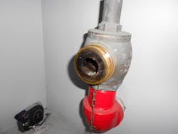
PRVs have an assortment of physical features making them easily discernible from standard unregulated standpipe outlets. For instance, while unregulated outlets have very smooth lines, PRVs are characterized by a wide bonnet under their valve wheel or by some other anomaly. And, they’re usually stamped with the words “pressure-reducing valve” or sometimes “pressure-control valve.”
The key concern for firefighters is that they cannot significantly increase a PRV’s outlet pressure by pumping into the system. So they must utilize hose/nozzle combinations compatible with the outlet pressure of the PRV to which they are connecting. Unfortunately, it has become increasingly difficult to know what that pressure might be. And here’s why.
The One Meridian Plaza fire seemed to be an awakening for the NFPA. It brought to their attention the fact that 2½-inch hose was no longer the standard attack line for the American fire service. Accordingly, they changed the standard in 1993, scrapping the 65–100-psi standpipe outlet requirement and changing it to a 100–175-psi range. This was intended for all new high-rise construction.
On the surface, knowing these facts would seem to make hose choice for high-rise fires simple. For buildings built before 1993, outlet pressures should be between 65 and 100 psi, so large-diameter hose would seem the best choice. Buildings built after that should have outlet pressures more compatible with smaller diameter hose—100 to175 psi. However, circumstances have rendered that logic futile.
At some point in the last decade or so, sprinkler/standpipe companies have started combining the two NFPA standards so that you may find standpipe outlet pressures ranging from 65 to 175 psi in the very same building, sometimes from one floor to the next.
This amalgamation of standards is further complicated by the continued existence of very old buildings with gravity tank standpipe systems. Outlet pressures at the upper levels of those old buildings are in the 25-psi range. Additionally, due to some sprinkler/standpipe mechanic’s tendency to stretch the limits of the pressure ranges, you might find outlet pressures in your buildings anywhere from 20 to 180 psi.
So it’s easy to see how dependence on one particular hose/nozzle combination for any high-rise fire is a big problem. Yet some departments’ standard operating guidelines (SOGs) mandate the use of 2½-inch hose for all high-rise fires while other departments still put all their eggs in the 1¾-with-automatic-nozzle basket. Clearly the large hose will be dangerous to operate at the higher range of pressures while the small hose connected to PRVs flowing lower pressures will be useless. Either way, the outcome could be disastrous.
Preplanning is key
Smart, proactive departments will provide their firefighters with the flexibility to operate effectively from any standpipe outlet in their city. But because firefighters need to know the appropriate hose/nozzle combination before leaving their apparatus, they need to know the outlet pressures for every standpipe outlet in every building. That means preplanning.
How can they determine outlet pressures through preplanning? First, and most emphatically, do not try to do it by simply asking property managers or building engineers for the pressures. They will not know the answer and will not know how to find it. But they can provide documentation that enables firefighters to determine riser pressures at every floor level.
Here’s how it works: All buildings are required to have their fire pumps officially tested at regular intervals. When done, the company conducting the test provides the building engineer (or property manager) with an official fire pump test report. That report shows the pressure generated by the pump while running with no water flowing (churn pressure) and the pump pressure when one, two and three 2½-inch handlines are flowing.
The fire officer conducting the survey gets a copy of that pump report and uses it to begin determining the riser pressure at each floor level served by that pump. That begins with the pump’s churn pressure, which is the maximum pressure generated by the pump (running but with no water flowing). All facets of a standpipe system are based on the churn pressure (PRV settings, sprinkler piping, riser pipe pressure rating, etc.).
At the fire pump’s floor level, the pressure in the standpipe riser is equal to the pump’s churn pressure. From there, the riser pressure decreases by 0.434 psi for every foot of rise due to the decrease in head pressure. The average floor height in office towers is 13.5 feet so the riser pressure drops by about 6 psi per story. So if a fire pump with a churn pressure of 200 psi is on the first floor, the riser pressure at the second floor is 194 psi, the third floor is 188 psi and so on to the top of the riser.
The average floor height in residential buildings is 10 feet, so the pressure drop in risers of those buildings is about 5 psi per floor. So if the fire pump on the first floor of a 20 building has a churn pressure of 200 psi, the riser pressure at the very top of the building will be about 100 psi.
Although determining the riser pressure at each level gives you the outlet pressures of unregulated standpipe valves, unfortunately, it does not give you the outlet pressures of PRVs. For those pressures, you must acquire another test report from the building engineer.
NFPA standards require PRVs to be flow tested every 5 years, and most municipalities follow suit. When those tests are completed, the service company provides the building with a PRV test report. It will typically list both the static and full flow pressures of each PRV standpipe outlet in the building. You are looking for the full flow pressure, of course.
But if the valves haven’t been tested or if the report is not available, it is impossible to accurately determine PRV outlet pressures without flow testing them yourself. Logic would suggest that if the outlets on the upper floors are unregulated and you determine their outlet pressures to be between 100 and 175 psi, the PRVs below them would be set to provide the same pressure range. But such logic cannot be relied upon.
For example, a 29-story building I surveyed in Houston had PRVs up through the 15th floor with unregulated outlets from 16 to the roof. Churn pressure derived figures told me the unregulated outlet pressure on the 16th floor was 175 psi and at the top of the building around 100 psi. Reason would suggest that the PRVs would also be set in that pressure range. However, the PRV test report told me those valves were all set to flow about 65 psi. In this case, logic did not apply.
In sum
Hopefully, by now it is undeniable that dependence on a single hose/nozzle combination for all high-rise fires is dangerous business. What works well in one building may prove nonfunctional in another. Consideration of nozzle pressure requirements, friction loss in and performance at wide ranges of supply pressures is imperative.
The real key to solving this dilemma is to visit your buildings—beginning with the unsprinklered high-rises—to find out what kinds of pressures you’ll get from every standpipe outlet. If you find a building where the fire pump seems to be producing pressures well above 175 psi yet there is no sign of PRVs, you should assume there are in-line PRVs in play somewhere. It sometimes turns into an interesting puzzle—a puzzle well worth solving.
A note of caution: Do not mistake the gauge reading at a building pump’s discharge for the churn pressure. A small jockey pump maintains system pressure 24/7, and the main pump only turns on when the system pressure drops below a certain level. When it does, it builds pressure to a level well above that maintained by the jockey pump. Insist on the pump test documentation.
Matt Stuckey
Matt Stuckey is a 36-year retiree of the Houston Fire Department. As a frontline downtown district chief, he became an ardent student of high-rise systems and of the details and outcomes of actual high-rise fires. Both before and after retirement, he worked 20 years for a leading high-rise life safety consulting firm, studying the systems in hundreds of buildings across North America. Stuckey has published two books, the latest of which is titled Firefighters and Highrises, 2nd Edition.
