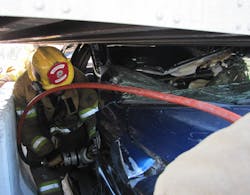
With every dash-manipulation technique, the success of rolling, pushing or lifting the dash greatly increases when the rescuer captures and manipulates the structural member that supports the dash system. This component is commonly referred to as the dash cross-member. It runs behind the dash components and is connected to the rest of the vehicle structure at the base of each A-pillar where the A-pillar transitions to the hinge pillar.
Because the dash cross-member is connected to and supported by the top of the hinge pillar, the hinge pillar is usually the contact point for the spreaders or ram during most dash manipulation techniques. Whenever force is transferred from one component to another component, there can be challenges. With this in mind, the intent of this article is to give you another option for performing a dash manipulation by separating these two components and manipulating them independently.
The technique
In the early 2000s, auto manufacturers started to expose the bolts that hold dash cross-members in place. The bolts are usually covered by some sort of plastic plug pressed into the sheet metal. Once the door is removed, these plugs can be removed easily with a simple hand tool (Image 1). Once the covers are removed, the bolt heads will be exposed. The bolt heads will most likely be a hex type, but they can also be Phillips, Allen, or Torx. A cordless impact with multiple drivers would be a great addition to a tool complement to handle this step, but simple hand tools also work well (Image 2). If access is not restricted and the bolts can be removed, simply loosen and remove the connecting bolts. If the bolts cannot be removed, the technique in this article will still work; the ram will just have to overcome the connecting bolts and bracket during the push. Remember that these bolts and the dash cross-member are designed to resist compression from side impact. Force applied by a ram or spreader will be 90 degrees to the engineered design and the bolts and/or bracket will fail.
A ram anchored to the B-pillar/rocker channel transition using a ram support bracket works well for this technique. Another option is anchoring the ram to the rail that the seat track is mounted to (Image 3). When anchoring to the seat rail system, you need to anticipate that the seat will also be pushed down and toward the rear seat area. This may be a good thing, as moving the seat along with the dash might be beneficial to the needs of the victim. The moving ram head needs to get through the soft dash components and make contact with the dash cross-member (Image 4). The soft dash components are easily removed using a prying tool, like a Halligan. Once the soft dash components have been weakened or removed, align the moving ram head to line up with the center of the dash cross-member. Once the ram head is centered on the dash cross-member push the dash cross-member to achieve the desired clearance (Images 5 & 6). A real plus with this technique is that the dash cross-member and all of the connected components will stay in place when the ram is retracted.
Another anatomy component that could cause some challenges during this technique is the dash cross-member down strap (Image 7). The down strap anchors the dash cross-member to the transmission hump or floor structure. When intact, the down strap will cause the dash cross-member to bend at the down strap connection point when it is pushed. Because the needed clearance to free a victim is usually achieved when the dash cross-member is bent at the mid-point, this is normally a non-issue. If a larger section of the dash needs to be pushed to free the victim or victims, expose the down strap and un-bolt or cut it. Once the down strap is disconnected, the entire dash from driver’s side to passenger’s side should move when the dash cross-member is pushed.
The second step of this technique is to displace the A-pillar and hinge pillar. Now that the hinge pillar is no longer connected to the dash cross-member, it is possible to pivot the hinge pillar and the A-pillar completely out of the vehicle. To accomplish this, first make three release cuts—one in the A-pillar (Image 8), one in the front clip between the strut tower and the firewall, and one in the hinge pillar just above the rocker channel (Image 9). Once the release cuts have been made, anchor the ram to either the B-pillar/rocker channel transition or to the rail that the seat track is mounted to. Align the moving head of the ram to make contact with the hinge pillar so it is forced out of the vehicle (Image 10). Pivot the hinge pillar and A-pillar out of the vehicle by extending the ram (Photo 11).
Final notes
Just like all vehicle rescue operations, this technique needs to begin with proper vehicle stabilization, SRS neutralization, and propulsion neutralization. And just like all hydraulic tool techniques, this one requires the removal of interior panels to expose any and all components that should be avoided during cutting and spreading operations. Like all new techniques, this one needs to be worked through in a training setting. One more thing: This technique is in no way intended to be “the way”; it is simply a technique that can be added to your standard operations that could help you succeed out in the real world. I call this another tool in the mental toolbox. As always, stay safe and happy cutting.
About the Author
Randy Babbitt
Randy Babbitt is a fire captain with the Huntington Beach Fire Department in Southern California. A 27-year fire service veteran, Babbitt has been instructing auto extrication, vehicle rescue, vehicle anatomy, alternative fuel technology, commercial vehicle rescue, mass transit rescue and technical rescue for more than 18 years.
