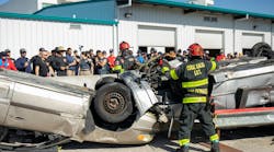
Once members have established that a rescue scene can be accessed safely and a proper size-up has been completed, it is time to assemble the air bag system. The information gathered in the size-up is used to determine which size air bags will be utilized and the optimal point(s) for lifting. It is critical that members properly assemble the system to ensure a safe and efficient operation.
The Lift Stack
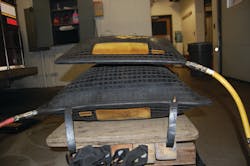
Part 2 of this series explained that the lifting capacity of an air bag decreases as the lifting height increases. This is because an air bag takes on a pillow shape as it inflates, and the entire dimensions of the bag no longer make full contact with the solid surface below or with the object to be lifted. As the actual working surface making contact with the object being lifted is decreased, it results in a reduction of the lift capacity of the bag (see Photo 1).
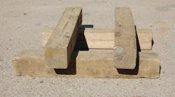
The size-up information that was obtained regarding the weight of the object and the best point(s) for lifting will help determine if a lift stack needs to be assembled and used in conjunction with the air bags. A lift stack is similar to a regular crib stack in construction, but it has a solid top tier (see Photo 2). A lift stack supports the air bags and places them closer to the object that is being lifted. This allows for inflation reduction, which maximizes the surface area making contact and thus allows the bag to lift at a greater capacity. Having good contact with the solid surface of the top tier also increases the lifting capacity of the air bag. Remember lift capacity is determined by the air bag surface contact with both the object being lifted and the supporting base material.
If regular crib stack construction is used, the air bag will start filling the gaps between the supporting timbers as it inflates, and this could potentially cause the timbers to shift and the stack to fail. If possible, a solid piece of plywood should be placed on top of the lift stack to ensure the air bags do not compromise the stability of the timbers in the system (see Photo 3).
Air Bag Placement
Once the lift stack is built, it is time to place the air bags. Members should use the size-up information to select the proper bag that can lift the weight and fit into the area. When placing air bags, it is best to stack two bags on top of each other; a large bag would be placed below a smaller bag. This stacking allows for added lift height if it is necessary to complete the objective. It is preferable to place two bags initially even if it appears both will not be required. The operation is greatly delayed if members have to deflate the air bag and build the lift stack higher to achieve the proper lift.
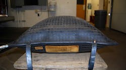
The air bags should be placed so that the air supply nipples are in opposite corners (see Photo 4). Try to connect the air bags to the pneumatic hoses, or to the remote shutoffs before placing them. This eliminates the hazardous situation of having members reach under the load to connect the hoses. The lower air bag should be placed with the nipple on the left side, and it should eventually be connected to the left side of the controller. This allows members to Lift – Lower – Left first. This is especially useful in low visibility environments where it may be difficult to see the color of the hoses when calling the lift.
When placing air bags, they should be centered on top of each other, as well as at the object’s lift point. It is critical that they are placed as close to center as possible to avoid shifting of the load or having the bags “kick out.” If there is any concern about potential damage due to contact with sharp edges, the bags should be protected with either commercially made products or pieces of rubber (see Photo 5). Conveyor belt rubber or large truck mud flaps work well for this. Hard materials such as plywood should be avoided, as it is best to have the air bags form around the object.
Assembling the System
All components that were discussed in Article 1 of this series need to be assembled. Prior to assembly, it is vital that members check that all pneumatic valves are closed to make sure an uncontrolled lift does not occur. Members should check the air supply valve on the regulator, the dead man switches on the controller, and possibly the closing of the remote shutoffs to the air bags.
Members should begin by attaching the regulator to the air supply. The air supply should not be turned on at this point. Members should recheck that the inline air supply valve on the regulator is in the “off” position. The pneumatic hose going to the controller will be attached to the regulator. The controller’s dead man switches should be cycled to ensure they are not sticking open. Attached to the controller will be the pneumatic hoses, or remote shutoffs (or pigtails) then pneumatic hoses, leading to the air bags themselves. The air bags should be connected to the hoses prior to placement. Try to have different colored hoses going to each bag to make calling the lift easier. As discussed earlier, have the lower bag’s hose attached to the left side of the controller. Additional information on calling the lift will be covered in the next article.
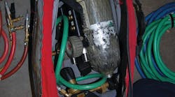
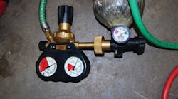
Once everything is connected and the valves have been double checked, members can turn on the air supply. The gauge on the regulator closest to the supply is the high pressure gauge; it should read the same as the air supply’s gauge. The regulator gauge farthest from the air supply is the low pressure gauge, and adjusting the large knob on the regulator sets the operating pressure (see Photo 6). The operating pressure should be adjusted to the manufacturer’s recommendation, which is stamped on the air bags themselves. Do not keep the regulator pre-set to the operation pressure. Keeping the operating pressure set all the time will eventually weaken the regulator spring to the extent that it cannot achieve the desired pressure.
After the regulator is set, the inline air supply valve going to the controller can be opened. Once it is open, readjust the operating pressure as needed. At this point the system is ready to inflate the air bags using the controller. If remote shutoffs are in place, they will need to be opened to allow airflow.
Conclusion
It is important that members understand how to build a structurally sound system to maintain stability and how to safely place the air bags. Without proper placement of the air bags, the load can shift or the air bags can “kick out,” which could potentially prove fatal. If the system is not assembled correctly, uncontrolled lifts can occur that could place victims and rescuers in danger. A properly constructed system will allow for a smooth rescue operation and will result in a safe outcome.
For the full series of Air Bag Operations
