Engine Company Apparatus Design Considerations: The Pump Panel
There are numerous questions to answer when setting out to develop baseline requirements for a new engine. There might be a wide range of interests in what personnel believe is important from an operational perspective.
For example, a driver might focus on interior dash panel layout and windshield visibility; the officer will have concerns about the amount of space on the right side of the cab and access to forcible entry tools; crew members will have opinions about the arrangement of rear cab seats, locations of handrails to permit safe access, and the height of crosslay and rear body attack lines.
A number of years ago, I had the opportunity to ride with a big city engine company that ran more than 4,500 responses annually. After the fifth call of the morning, I sat down with the crew and inquired what they considered to be important in the design of their engine. I expected comments relative to the operational character of the rig. However, the response was something like this: “Comfortable, forward-facing seats, big cup holders and strong refrigeration,” referring to the capabilities of the air conditioning system. So much for thinking that I was going to learn about the vehicle’s acceleration or hear comments about the lack of scene lighting.
This reinforced the idea that it’s vital to solicit input from those who are responsible for the operation of the apparatus. It can assist the apparatus committee to develop specifications that meet the department’s mission while also addressing concerns that will enhance the in-service time of the vehicle and reduce unwanted mechanical repairs.
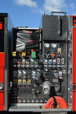
Pump panel & piping
Once the apparatus committee determines the required fire pump and water tank size, the job of designing the pump panel and piping configuration can take place. The engine company driver is one of the most important personnel on the fireground; this individual is responsible for obtaining a continuous and reliable water supply and for ensuring that the first attack line gets water when called for. The layout and design of the pump panel is one of the most important pieces of real estate on the vehicle but often is overlooked during specification.
Many manufacturers have a standard pump panel design, to include piping runs and termination points for discharges. The location of major controls, such as the governor, the throttle, the tank to pump, the tank fill and the master gauges, often are in different areas, as determined by the manufacturer’s engineering staff based on manufacturing efficiencies and predetermined standard locations. However, the apparatus committee should specify the location of certain pump instrumentation, suction, discharge valve controls and other components. The pump panel design on an apparatus should be laid out in a logical fashion that meets the operational needs and standard operating guidelines of the department, and the preconstruction conference is the time to review how the pump panel gauges, intakes and discharges will be laid out, considering the width of the pump panel and the degree of complexity of the pump system, including foam systems.
The department should include requirements with its bid, so the manufacturer will provide a detailed layout of the pump panel at the preconstruction conference for review and approval. That said, this documentation isn’t provided as standard, and in some instances, there is a cost to this level of detail.
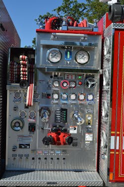
When compared with manual pull rod controls, or gear-operated valves, the use of electric valve controllers can reduce the size of the pump panel, because the manually operated valves require straight line runs from the panel to the valve. Consideration of access points to manually override the valve in the event of the occurrence of an electrical malfunction might be necessary.
A trend is to utilize pedestal-style fire pumps that have compact suction and discharge manifolds. These can shrink the size of the panel and, when combined with electric valve controllers, can require half of the space of the traditional pump panel. If this design permits a department to carry more equipment or reduce the overall length of the apparatus, it might have merit. When evaluating this style of pump panel design, pay attention to the location of intakes and discharges and their capability to support large-capacity fire flows via multiple large-diameter intakes and a minimum of 4-inch full-flow valves and piping for large-diameter-hose discharges.
Intakes & discharges
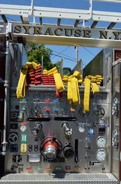
The position and size of intake and discharge gauges should be considered in pump panel design. Master gauges are available in 4½- and 6-inch sizes with different pressure ranges. This is particularly important for discharge gauges that the apparatus industry largely has standardized on smaller 2½-inch gauges with a pressure range of 300–600 psi. There is a nominal cost difference to provide the larger gauges.
If a department utilizes crosslay or transverse hosebeds, the height from the ground and the clear width of each hosebed should be specified. Transverse hosebeds should be no more than 62–64 inches from the ground. Anything higher would make it unsafe for the crew if it needs to step up on the pump panel to pull and advance an attack line. How a department loads attack lines has an effect on how the transverse beds should be arranged as well as the position of the discharge piping. Consideration should be given to having the transverse bed discharge terminate directly under the respective hosebed. This location permits rapid extension of the line and reduces the friction loss in the chiksan swivel.
To develop rated pump capacity, engines should be designed with multiple large-diameter intakes to supply the fire pump. Whether using front, side or rear suction inlets, these should have the capability to control at least two from the left-side pump panel area. The utilization of a power-operated valve that has an air bleeder and manual override enables the pump operator to control the water supply without that individual having to run around to the other side of the apparatus.
The location and length of attack lines depend on the response district that a department serves and the standard staffing for the engine company. Some departments rely on multiple preconnected attack lines, which can range in length from 100–400 feet, with static bulk beds or 2½- or 3-inch hoseline to fill out extended hoselays. A standard attack line complement can be integrated easily into the vehicle design.
A final consideration in the realm of the design of the pump panel should be having adequate panel and scene lighting to illuminate the left- and right-side areas of the panel. This lighting should be extended to the top area above the pump, particularly if the unit is equipped with a deck gun or wagon pipe. The reason for this: The output of the apparatus manufacturer’s standard lighting configuration might not be sufficient to illuminate all of the working area.
A concerted effort
One of the greatest challenges for the apparatus committee is to carefully determine the desired panel configuration that will meet the operational and training needs of the organization—not just throw all of the components into the smallest available space. The engine company driver has one of the most important jobs on the fireground. Anything that you can do to make this person’s job safer and easier greatly will enhance the overall operation to ensure success.
About the Author

Tom Shand
TOM SHAND, who is a Firehouse contributing editor, is a 36-year veteran of the fire service. He works with Michael Wilbur at Emergency Vehicle Response, consulting on a variety of fire apparatus and fire department master-planning issues. Shand is a member of the Firehouse Hall of Fame.