Shoring Systems for Structural Collapse - Part 1
This month we are going to discuss shoring operations. We’ll take a look at a few different shoring systems and not only break down the construction of them, but also cover the principal behind which all shoring systems are based.
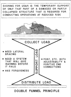
There are probably more than a dozen shoring systems we work with, but the engineering concept behind them all is the same. Yes, that’s right, I said the same. It’s called the double-funnel principal (see Figure 1). The whole concept behind a shoring system is to capture the target load (point A) and transfer it to the ground (point B). It sounds simple, doesn’t it?
While the concept is simple, it takes a lot of training to learn how to construct these systems properly and in a timely fashion. The double-funnel principal is based on transferring a load from point A to point B in a straight line. It all comes down to basic physics. The load is going to go where it wants to go, so it’s our job to direct it where we need it to go, which is the ground.
Crib Stacks
Let’s start off with the most basic of shoring systems, the crib stack. As simple as it is, there are rules you need to follow.
- The height of the crib stack can be no higher than three times the width of the stack
- The overhang of the lumber should be no more than the diameter of the wood.
- Each layer of the stack needs to line up with its matching layer.
- The stack can be no more than 30 degrees out of plumb.
The weight-supporting capabilities of a crib stack are tremendous. To give you an example, a four-member crib stack built using 4x4 lumber can support 24,000 pounds. The same crib stack constructed from 6x6 lumber can support an impressive 60,000 pounds. Those are some great numbers if you ask me. Cribbing is made from composite plastic/rubber and wood and the minimum length of each piece should be 24 inches. Wood is the material of choice when constructing shoring systems because of its outstanding load-carrying capabilities and the fact that when lumbers exceeds its load-carrying capabilities it will give collapse warning signs, such as creeks, groans and visible crushing on the header and sole plates.
The Double “T” and Vertical Three Post
The Double “T” shore (see Figure 2) has replaced the “T” Spot shore for many rescue teams, purely based on the fact that the load-carrying capabilities are four times that of the “T” Spot (16,000 pounds as opposed to 4,000 pounds at 8 feet high) and it’s more stable than the “T” Spot. Also, the “T” Spot is a temporary shore where as the Double “T” is not.
Let’s now build off of the Double “T” and segue into the Vertical Three-Post shore (see Figure 3). As with all vertical shoring systems, we want to align the uprights (vertical members) with the floor joists above. If you think about it, this makes sense since we’re trying to transfer a load through the shoring system into the ground. One major rule pertaining to these vertical shoring systems is if your shoring operation is being conducted in a wood-frame building, you must not only shore the initial floor your working on, but one floor below. That’s two shoring systems perfectly in line with each other. If your building is concrete, you will need to shore two floors below.
The rectangular pieces of wood nailed to both the vertical and uprights of the shoring system are called gusset plates. These are used to connect the uprights to the sole plate and header. Specific nail patters have been developed by engineers taking into account the shear strength of the nails being used, the psi rating (pounds per square inch) of the lumber, as well as the psi used to nail the plates to the lumber (120 psi).
Take another look now at the bottom of the uprights or vertical members. You should see pairs of wedges placed between the vertical (upright) and the soul plate. The principal behind these wedges is rather simple. When we build our shoring system, we don’t build it to fit the placement space exactly. It’s rare that you have something perfectly level to shore, which would allow you to build a system exactly to spec. So, we leave off 1 1/2 inches from our measurement to allow us to place the wedges under each upright and tap them together until the system as a whole is firmly in place. Once we’re satisfied, we’ll take a 16D nail and toenail it behind each set of wedges (both sides) to prevent any possible slippage. When taking measurements for the verticals, you must subtract seven inches if using 4x4 lumber and 11 inches for 6x6 lumber from the total height measurement to allow room for the sole plate and the header.
Remember, all of our shoring must be perfectly plumb once they’re set in place and we need a plumb vertical path for our load to be transferred through. Here’s an easy way to understand this. Take a piece of cribbing and place it vertical, perfectly straight up and down. Now place your palm on top of the ruler and apply a good amount of pressure. The cribbing should not move. Now perform the same exercise, but place the cribbing out of plumb, the cribbing should kick out under the pressure due to the fact that there was no straight path of travel for our load force to follow. It’s a simple demonstration, but it really does a great job explaining this concept.
Lace Post
If you take a close look at a Lace Post shore (see Figure 4), it’s actually two vertical shores laced together. Lacing can be constructed by using 2x4 lumber or 2x6 lumber. The vertical lacing will help to counteract forces that could cause the system to rack (collapse forward on itself). The cross bracing you see helps counteract any torsional loads/forces that are placed on the system. The cross bracing should be installed so that whichever side of the shoring system you look through it forms an “X”. By doing this, you give the system equal torsional resistance on all four sides. Lace Post shoring systems are one of, if not the, strongest shoring systems you can build and are often used to support heavy loads such as a floor in a parking deck. Of course, based on the size load you’re supporting, you may need to build a few to cover the desired area.
Throughout this article you’ve read about gusset plates, vertical bracing and cross bracing. Installing these features is not as simple as throwing some nails in the wood and calling it a day. Everything we nail has a pattern assigned to it and for good reason. Engineers did testing on shear load ratings on different size nails, and strength ratings on the wood based on type, psi, and its ability to retain its integrity when nails were placed in it. Through that testing, these nail patterns were developed. Here are a few:
- 2x4 lumber – three 16D nails @ 120 psi
- 2x6 lumber – five 16D nails @ 120 psi
- ¾-inch plywood gusset plate 6? x 12? – four 8D nails @ 120 psi
- 12x24 top gusset plate used in a Double “T” shore – 17 8D nails horizontally and five 8D nails vertically @ 120 psi
- 12x24 midpoint gusset plate used in a Double “T” shore – eight 8D nails on each upright @ 120 psi
All the shores will have subtle changes as the height increases, such as brace placement or the dimension of lumber used. Engineers have developed what is called an LD Formula. This formula tells us how long a piece of lumber can be and still accept the load safely. A great example of how this works on a small scale is to take two wooden rulers and cut one at the six-inch mark and leave the other a foot long. Place the foot-long ruler vertical and with your hand apply force to the top. You’ll see the ruler bow and flex. The load you’re applying clearly exceeds the load-carrying capabilities of the ruler. Now perform the same experiment on the six-inch piece. That piece should be able to carry the load you’re applying. On a small scale, one conforms to the LD Formula one does not. Here is a breakdown of the LD Formula.
Engineers work with two numbers ¬– 25 and 50, with 50 being the high end of the scale, the number that lives on the edge and the number that will maximize the allowable vertical height and still operate safely. For this example, we’ll use 25. That will give us the length of a 4x4 at its peak load-carrying capacity.
25 x 3.5 (dimension of a 4x4) = 87.5
87.5 / 12 = 7.291... Let’s just say eight feet.
A 4x4 at eight feet in length has a capacity of 8,000 pounds. That same 4x4 with a length of 12 feet (max. length) has a capacity of 3,500 pounds. If your verticals need to be 12 feet in height, you are better off using 6x6 lumber. A 12-foot piece of 6x6 lumber has a vertical capacity of 20,000 pounds. That’s a big difference.
Different operations will call for different shoring systems. Knowing the limitations and abilities of your systems will be imperative to a safe and successful operation. You we’re introduced to a few different systems this month and we’ll cover a few more next time. Take some time to look at the images in this article. Breaking down a system piece by piece is a great and fast way to develop a greater understanding of this discipline.
Remember...“Training Prepares You for Moments That Define You!”
MICHAEL R. DONAHUE is a 14-year veteran of the fire service assigned to Rescue Company 1 in Elizabeth, NJ. Mike is the owner and founder of Progressive Rescue, a company dedicated to further firefighter's in all aspects of the job. He holds the title of rescue specialist with New Jersey's Urban Search and Rescue Team (NJ-TF1) and he is actively teaching at Middlesex Fire academy and the Middlesex County College as their Fire Science Program Coordinator.
About the Author

Michael Donahue
Owner and founder of Progressive Rescue, Mike Donahue is a 13-year veteran to the fire service. In those thirteen years Mike has experience as both a volunteer and federal firefighter and has been a career firefighter in the City of Elizabeth for the last 10 years, the last seven of which and currently working out of Rescue Company 1. Mike holds the title of Rescue Specialist with New Jersey's urban search and rescue team (NJ-TF1). You can find Mike actively teaching at Middlesex and Somerset Fire Academies as well as Middlesex County College as an Adjunct Professor and the Fire Science Program coordinator. He is actively involved in writing new course programs for the various organizations he teaches for. Mike has reviewed several text books for publishers such as Delmar and Jones & Bartlett. Mike has also co-written the new rope program for Jones & Bartlett and taught Rope Rescue Made Simple at Firehouse Expo 2010. Mike also is a monthly columnist for Firehouse.com covering the area of technical rescue. His teaching techniques and cutting edge style have gained the respect from many of his peers. Mike's passion, experience and desire to educate emergency service providers prove to be the driving force that has made him so successful. Progressive Rescue prides itself on providing the most cutting edge, diverse instructional programs available. We strive to provide your department with the most comprehensive, dynamic learning experience available at a truly competitive price. You can reach Mike by e-mail at [email protected]