Station Design Supplement: HVAC Design to Support Hot Zone Design
Published research on cancer rates in fire station staff has given rise to a new design philosophy among fire station architects.1 Hot Zone Design was developed to prevent the entrainment of contaminants from areas inside the station that are identified as sources (apparatus bays, decontamination areas, etc.) into the living quarters.2 Now, simultaneous modifications to the heating, ventilation and air conditioning (HVAC) design can complement and support hot zone design.
The contaminants identified as cancer-causing include benzene, formaldehyde, butadiene, toluene, acrylonitrile and isocyanates, among others. These chemicals are emitted as gases and soot during a fire, and contaminate exposed gear, vehicles and tools.
When firefighters return to the station with contaminated equipment, they follow industry-standard practices for decontamination, which take place in specific locations within the building. These immediate and essential steps to control contaminants include washing vehicles, apparatus and gear. Depending on the location of the contaminated equipment, wash locations, and the route of travel between the spaces housing the equipment and the living quarters, contaminants may have a direct path of transmission into the living quarters. Transmission routes haven’t been studied in detail, but may take place physically on people and clothing, and potentially through the transfer of air. HVAC design can help address the latter.
Hot zone design
Areas of the station where the exposed equipment is stored and washed are identified as hot zones. Areas that are required to be contaminant free are named cold zones, and the spaces between are transition zones. Architectural hot-zone programming consolidates the spaces within each of the hot and cold zones, and provides controlled transitions between the zones. Hot zone design philosophy complements the fundamental fire station design practices of providing the most direct path to respond to an emergency call and grouping similar usage areas.
HVAC systems must support the objective of hot zone design by limiting transmission of contaminants from the hot zone, through the warm (transition) zone, and into the cold zone. To achieve this goal, the HVAC engineer should view the mechanical systems not as individual components, but as a unified configuration that integrates all aspects of the required building operations.
Contaminant transfer is inhibited and limited by HVAC systems through several means (each may be employed individually or in some combination):
- Positive space pressure control to prevent contaminated air from entering a space. A room can be put into positive pressure by supplying more air than is exhausted. A positive space will move air out of the room, either under the door when the door is closed, or through the doorway when the door is opened. Positive pressure control is typically utilized in cold zones.
- Negative space pressure control to contain contaminated air and prevent transfer to other spaces. A room can be put into negative pressure by exhausting more air than is supplied. A negative space will draw air in from surrounding spaces to make up the differential between the exhaust and supply. The air to make up the exhaust can be transferred under the door, when the door is opened, or through overhead transfer ducts and grilles that connect positive and negative spaces. Negative pressure control is utilized throughout hot zones.
- The 100 percent outdoor air equipment provides a single pass-through of outdoor air that is exhausted without being mixed and returned to the space. This system and equipment type is typically used in all hot zones to remove contaminants. The equipment will be balanced to provide more exhaust than supply so that the space served is under negative pressure.
- Exhaust air from equipment serving hot zones must not be re-entrained into the outdoor air intakes of equipment serving cold zones. This will often require exhaust and intakes to be more than the code minimum distances apart. A good practice is to evaluate local wind direction data.
Common to both positive and negative space pressure control is the requirement for the differential between supply and exhaust airflows to be sufficient enough to move air through doorways, but not impact the operation of the door. A common target is to develop between 0.04-inch water gauge (w.g.) and 0.07-inch w.g. As a reference, NFPA 92 smoke control stairwell pressurization must generate a minimum of 0.1-inch w.g. across the stairwell door.
HVAC design criteria
To realize a fully integrated HVAC design that addresses hot zone design, it is necessary to identify the design criteria on two increasingly complex levels and perform a final system integration analysis. This work should be performed during the schematic design phase in conjunction with the architect and continue through the development of the 100 percent construction documents. Starting work during the schematic and programming phase will permit the engineer to identify any potential issues with the initial layout. Issues may be as basic as not having sufficient space for the equipment to service the rooms and zones properly, or could be more complex and involve relocations of rooms and doors.
Stages of design for hot zone HVAC design: 1) Room Criteria, 2) Zone Criteria and 3) System Integration Analysis.
1. Room criteria
Room criteria are often well-documented as part of the design narrative generated by the engineer during the schematic design phase. The basic needs of each room are identified and the conditions are frequently tabled. The engineer will identify the living-quarter occupied spaces, such as bunk rooms, dayrooms, kitchens and offices. The support spaces will also be identified and include the apparatus bay, decontamination rooms, gear storage rooms, laundry, shop tool rooms, etc. Each room’s designed heating and cooling temperature set points are noted, along with any upper and lower humidity requirements. Occupancy rates are documented with code-required ventilation rates.
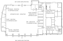
Critical to hot zone design is to include relative air pressurization in the room criteria. The room must be noted as either being under positive, neutral or negative pressure relative to the adjacent space. A space airflow diagram is often a great help in showing how each space pressure relates to adjacent spaces and showing airflow paths.
2. Zone criteria
Zone criteria tend not to be clearly documented on the design documents and may not be immediately obvious to the end user or owner, although they may be implicitly addressed in the design. Groups of rooms must now be identified and zoned. The zones should be labeled with their potential contaminant level as either hot, warm (transitional) or cold.
The zones and groups will then have specific systems and HVAC equipment associated with them. Decisions as to what type of system is most appropriate for each zone will be influenced by many factors: Ability to maintain space temperature and humidity set points, life-cycle cost analysis, availability of utilities, space constraints, energy efficiency, maintenance requirements, etc. Hot zone design adds additional factors that must be considered—airflow and space pressure control.
A typical fire station will likely have several zones with individual HVAC equipment and systems, divided among cold zones (bunk rooms, offices, training/multipurpose rooms, other rooms open to the public, kitchen and dayrooms, exercise rooms, and telecom/data rooms) and hot zones (apparatus bay, PPE storage room, SCBA storage room, PPE laundry room, decontamination room, and hose storage).
3. System integration analysis
After selecting the HVAC systems and equipment for each of the cold and hot zones and verifying they address all the room criteria, the engineer must now focus on the final task of ensuring that each part of the HVAC system is fully integrated with the building hot zone design and functions to hinder the transmission of contaminants between zones and rooms.
Each system and piece of HVAC equipment must be reviewed in context with the other systems in the fire station. Proper maintenance of space pressurization between zones must be confirmed. For example, this may include:
- Apparatus bay ventilation/exhaust systems relative to the living quarters space conditioning system
- Apparatus bay ventilation/exhaust systems relative to public space conditioning system
- PPE storage room ventilation/exhaust system relative to the apparatus bay ventilation/exhaust
- PPE laundry ventilation/exhaust system relative to the apparatus bay ventilation/exhaust
- Determine that the apparatus bay system is continuously under negative pressure. Continuous exhaust is a code requirement, but intermittent high-volume vehicle exhaust or additional summer ventilation will affect pressure and should be considered in every scenario examined.
- Ensure the living quarters HVAC system provides continuous positive pressure relative to the apparatus bay. In a 24/7 facility in which equipment operates with a fixed quantity of outdoor air, this shouldn’t be problematic. Complications arise when the system has unoccupied sequences or the outdoor air intake varies based on demand control ventilation. Again, the engineer should assess the system under each of the operating conditions.
- Continue the analysis of other zone equipment, sequences, and airflow variables if the living quarters are adjacent to other negative spaces such as the PPE room.
- Quantify the volume of air being exhausted from the apparatus bay and determine from where the make-up-air is being drawn. Make-up-air will be drawn not only from the living quarters, but from other adjacent spaces as well, as infiltration from doors and windows.
- Calculate the volume of air necessary to maintain target pressure levels across the doors between the living quarters and the apparatus bay. Perform this calculation for every combination of sequences for the HVAC systems involved.
- Verify the worst-case scenario is identified, accommodated by the equipment, and ensure operations in the other scenarios don’t create pressurization issues. Being too positive prevents doors from latching closed, and a very negative space may make it difficult to open doors.
- Finally, update the airflow diagram with the design airflow values calculated for the worst-case scenario and update HVAC equipment selections with revised outdoor air or exhaust values.
In sum
Hot zone design is gaining traction in fire station architectural design, and the HVAC engineer can support this design objective through equipment selection, equipment location, airflow control and space pressurization. A fundamental understanding of each space, its associated zone type, and all the room condition criteria are required at project commencement. After establishing individual room criteria, the engineer must continue the development of the design through the grouping of rooms to create zone criteria and the subsequent selection of equipment. HVAC design is only complete once the final system integration analysis is performed. This final complex task is critical to ensuring that the HVAC equipment will perform as an integrated system in support of hot zones design.
1. Daniels, R, Kubale, T, Yiin, J, et al. “Mortality and cancer incidence in a pooled cohort of US firefighters from San Francisco, Chicago and Philadelphia (1950–2009).” 2013. Occup Environ Med (published online first. doi: 10.1136/oemed-2013-1016621
2. Erickson, P. “Hot Zone Design: Contain the Contaminants.” 2014. Firehouse Magazine. Firehouse.com/11588372.
About the Author
Philip Wright
Philip Wright, LEED AP, serves as a regional manager for Brinjac Engineering. He has been involved in the design and commissioning of over 20 fire stations. Wright has a master’s degree in mechanical engineering, and is a registered professional engineer and a Certified Commissioning Professional.